Gate Valve Dn50 to Dn600
1) Product information: The gate valves supplied are mainly used for adjusting water, steam, oil, gas, and natural gas in chemical industries
2) Standards: AWWA, DIN3352 F4/F5, BS5163, BS5150
3) Connection type: Flanged type, push-on type, mechanical joint type, plain ends type
4) Material:
A) Body: Ductile Iron GGG500-7
B) Wedge: D/I, core fully vulcanized with NBR or EPDM rubber
C) Wedge Nut: Brass
D) Stem: Stainless steel, BS970 431S29 or DIN17440X20Cr13
E) Gasket: NBR
F) Bonnet: GGG500-7
G) O ring: NBR
H) Washer: Carbon steel or Stainless steel.
5) Size: 50-400mm/2" - 16"
6) Pressure grade: PN10, PN16
7) Coating:
A) Fusion-bonded epoxy 0.2-0.5mm inside and out side
B) Coating as per customers' requirement
8) package: Carton for each item, wooden boxes outside.
| Application | |||||||||
| 1 | Face to face is according to DIN3202-F4 | ||||||||
| 2 | Flange drilled is according to DIN2532/2533 | ||||||||
| 3 | Nominal pressure PN10/PN16 | ||||||||
| Test | |||||||||
| Working pressure | PN10 | PN16 | |||||||
| Shell pressure | 1.5MPa | 2.4MPa | |||||||
| Seat pressure | 1.1Mpa | 1.76MPa | |||||||
| Main Parts and Materials | |||||||||
| Number | Part Name | Material | |||||||
| 1 | Body | EN-GJL-250 | |||||||
| 2 | Seat ring | Brass | |||||||
| 3 | Wedge | CI+Brass | |||||||
| 5 | Wedge Nut | Brass | |||||||
| 6 | Stem | AISI 420 | |||||||
| 7 | Bonnet Gasket | EPDM | |||||||
| 9 | Bonnet | EN-GJL-250 | |||||||
| 12 | Stem Sealing | EPDM O Ring | |||||||
| 13 | Stuffing Nut | Brass | |||||||
| 21 | Dust Guard | EPDM/NBR | |||||||
| Main Dimensions | |||||||||
| Size | L | D | D1 | D2 | b | n-d | H | W | W.T |
| DN40 | 140 | 150 | 110 | 88 | 16 | 4-18 | 260 | 130 | 8.6 |
| DN50 | 150 | 165 | 125 | 102 | 18 | 4-18 | 265 | 130 | 10.9 |
| DN65 | 170 | 185 | 145 | 122 | 18 | 4-18 | 293 | 130 | 14.2 |
| DN80 | 180 | 200 | 160 | 138 | 20 | 8-18 | 318 | 150 | 20.3 |
| DN100 | 190 | 220 | 180 | 158 | 20 | 8-18 | 349 | 185 | 22.8 |
| DN125 | 200 | 250 | 210 | 188 | 20 | 8-18 | 416 | 185 | 33.9 |
| DN150 | 210 | 285 | 240 | 212 | 22 | 8-22 | 456 | 195 | 42 |
| DN200 | 230 | 340 | 295 | 268 | 24 | 8-22 | 537 | 225 | 63.4 |
| DN250 | 250 | 395 | 350 | 320 | 26 | 12-22 | 659 | 245 | 91.8 |
| DN300 | 270 | 445 | 400 | 370 | 26 | 12-22 | 718 | 285 | 138.6 |
Our gate valve photos Gate valve
1) Product information: The gate valves supplied are mainly used for adjusting water, steam, oil, gas, and natural gas in chemical industries
2) Standards: AWWA, DIN3352 F4/F5, BS5163, BS5150
3) Connection type: Flanged type, push-on type, mechanical joint type, plain ends type
4) Material:
A) Body: Ductile Iron GGG500-7
B) Wedge: D/I, core fully vulcanized with NBR or EPDM rubber
C) Wedge Nut: Brass
D) Stem: Stainless steel, BS970 431S29 or DIN17440X20Cr13
E) Gasket: NBR
F) Bonnet: GGG500-7
G) O ring: NBR
H) Washer: Carbon steel or Stainless steel.
5) Size: 50-400mm/2" - 16"
6) Pressure grade: PN10, PN16
7) Coating:
A) Fusion-bonded epoxy 0.2-0.5mm inside and out side
B) Coating as per customers' requirement
8) package: Carton for each item, wooden boxes outside.
| Application | |||||||||
| 1 | Face to face is according to DIN3202-F4 | ||||||||
| 2 | Flange drilled is according to DIN2532/2533 | ||||||||
| 3 | Nominal pressure PN10/PN16 | ||||||||
| Test | |||||||||
| Working pressure | PN10 | PN16 | |||||||
| Shell pressure | 1.5MPa | 2.4MPa | |||||||
| Seat pressure | 1.1Mpa | 1.76MPa | |||||||
| Main Parts and Materials | |||||||||
| Number | Part Name | Material | |||||||
| 1 | Body | EN-GJL-250 | |||||||
| 2 | Seat ring | Brass | |||||||
| 3 | Wedge | CI+Brass | |||||||
| 5 | Wedge Nut | Brass | |||||||
| 6 | Stem | AISI 420 | |||||||
| 7 | Bonnet Gasket | EPDM | |||||||
| 9 | Bonnet | EN-GJL-250 | |||||||
| 12 | Stem Sealing | EPDM O Ring | |||||||
| 13 | Stuffing Nut | Brass | |||||||
| 21 | Dust Guard | EPDM/NBR | |||||||
| Main Dimensions | |||||||||
| Size | L | D | D1 | D2 | b | n-d | H | W | W.T |
| DN40 | 140 | 150 | 110 | 88 | 16 | 4-18 | 260 | 130 | 8.6 |
| DN50 | 150 | 165 | 125 | 102 | 18 | 4-18 | 265 | 130 | 10.9 |
| DN65 | 170 | 185 | 145 | 122 | 18 | 4-18 | 293 | 130 | 14.2 |
| DN80 | 180 | 200 | 160 | 138 | 20 | 8-18 | 318 | 150 | 20.3 |
| DN100 | 190 | 220 | 180 | 158 | 20 | 8-18 | 349 | 185 | 22.8 |
| DN125 | 200 | 250 | 210 | 188 | 20 | 8-18 | 416 | 185 | 33.9 |
| DN150 | 210 | 285 | 240 | 212 | 22 | 8-22 | 456 | 195 | 42 |
| DN200 | 230 | 340 | 295 | 268 | 24 | 8-22 | 537 | 225 | 63.4 |
| DN250 | 250 | 395 | 350 | 320 | 26 | 12-22 | 659 | 245 | 91.8 |
| DN300 | 270 | 445 | 400 | 370 | 26 | 12-22 | 718 | 285 | 138.6 |
Our gate valve photos
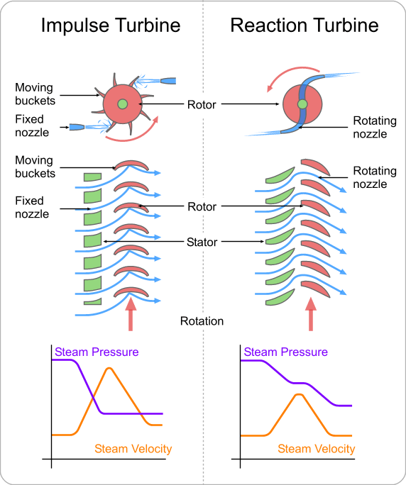
An impulse turbine is a type of Steam Turbine where the rotor derives its rotational force from the impact force, or the direct push of steam on the blades.
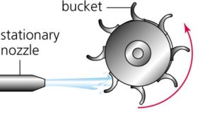
The impulse turbine consists of a rotor mounted on a shaft that is free to rotate. Attached to the rotor are a set of curved blades. Nozzles then direct the high pressure and high temperature steam towards the blades of the turbines. The blades catch the impact force of the rapidly moving steam and rotate from this force.

The Impulse Principle
The steam at high pressure enters through a stationary nozzle of a steam turbine, as a result the pressure of the steam is decrease and an increase in steam velocity. As a result of increased steam velocity steam pass through the nozzle in the form of a high-speed jet. This high-velocity steam hit the properly shaped turbine blade, as a result, the steam flow direction is changed. The effect of this change in direction of the steam flow will produce an impulse force. This force cause the blade move, thereby the rotor will start to rotate.
The force applied to the blade is developed by causing the steam to change the direction of flow (Newton`s 2nd Law – change of momentum). The change of momentum produces the impulse force.
Impulse Turbine Working:

In the impulse turbine pressure drops and the velocity increases as the steam passes through the nozzles. When the steam passes through the moving blades the velocity drops but the pressure remains the same.
The fact that the pressure does not drop across the moving blades is the distinguishing feature of the impulse turbine. The pressure at the inlet of the moving blades is same as the pressure at the outlet of moving blades.
Impulse Steam Turbine
Shandong Qingneng Power Co., Ltd. , https://www.steamturbine.be
